A packaging line can lose fill accuracy, seal quality and production time when compressed air is selected by horsepower alone. By mapping each air consumer, calculating simultaneous demand and specifying treatment at the point of use, you can match the compressor, receiver and filtration system to the line’s real operating conditions.
Key takeaways
- Size the compressor by required pressure and airflow, not horsepower alone.
- Use oil-free or treated air when product or packaging contact demands it.
- Match the receiver, controls and dryer to the line’s changing air demand.
- Specify pipe size, pressure drop, drainage and service access before installation.
Where compressed air works across a packaging line
A packaging line uses compressed air for both product movement and machine motion. Pneumatic product filling valves and dosing systems control liquid or powder flow; bottle handling and pouch handling rely on cylinders, clamps and grippers to position packs. Capping, lidding, labelling and carton forming then use actuators to apply force and timing.
| Air type | Typical uses | Main risk if contaminated or unstable |
|---|---|---|
| Product or package-contact air | Filling, bottle rinsing, pouch interiors, blow-off touching an open pack | Oil, water or particles can contaminate the product or package; pressure variation can alter dosing |
| Utility actuator air | Pick-and-place cylinders, capping heads, lidding arms, sealing-machine actuators and carton mechanisms | Slow or mistimed cylinders, weak clamp force, incomplete seals and misfeeds |
| Vacuum and process air | Vacuum generators for gripping or pack evacuation; nozzles and air knives for cleaning or transfer | Dropped packs, poor evacuation and excessive consumption from unrestricted blow-off |
At each station, pressure must hold at the regulator and valve manifold while machines cycle together. A pressure dip can cause inaccurate fill volumes, delayed bottle or pouch transfers, rejected packs and line stoppages. Poor flow also weakens sealing pressure and makes vacuum generation unreliable.
Before choosing an air compressor for packaging industry use, separate product-contact requirements from utility air. Specify filtration, drying and distribution for the first category independently; then size cylinders, vacuum generators and blow-off devices for their actual peak demand rather than raising plant pressure.
How to calculate pressure and airflow instead of choosing by horsepower
A compressor’s horsepower does not tell you whether a packaging line will hold pressure. Use this compressed-air sizing method instead: measure demand at each consumer and specify pressure at the machine inlet under flow.
For every filler, sealer, actuator, vacuum generator and blow-off point, record:
- Required inlet pressure in bar(g)
- Free air delivery in m³/min or CFM
- Duty cycle and operating hours
- Average flow, cycle duration and peak demand
Do not compare free air delivery with normal litres per minute, standard cubic feet per minute or actual volumetric flow until every figure uses the same reference pressure, temperature and moisture basis. Otherwise, a catalogue value and a machine datasheet can appear compatible while understating the required compressor capacity.
| Flow label | What it represents | Sizing action |
|---|---|---|
| Free air delivery | Reference-condition compressor output | Compare only with matching reference conditions |
| Normal litres per minute | Flow converted to a stated normal condition | Confirm the specified temperature and pressure |
| Standard CFM | Flow converted to a stated standard condition | Check the standard definition before conversion |
| Actual volumetric flow | Volume at the machine’s real pressure and temperature | Convert to the selected reference basis |
Add the demands of machines that run simultaneously, then model synchronized actuator cycles, intermittent blow-off and vacuum peaks. Include a documented leakage allowance based on a measured leak test, not an arbitrary percentage.
Pressure losses through filters, dryers, regulators, hoses, couplings, valves and piping count against the inlet requirement. A receiver can cover a short spike, but it cannot replace continuous compressor flow; specify the minimum pressure at the machine inlet while the line is operating.
How air quality protects products, packages and pneumatic components
Specify air quality as ISO 8573-1 particle/water/oil classes, plus the sampling location: “ISO 8573-1 Class 1:2:1 at the filler nozzle.” Class 1:2:1 is not equivalent to Class 2:1:1. Set a separate grade for product-contact or package-interior air; cylinders, valves and actuators using utility air do not automatically need that grade.
A hazard analysis or customer standard can require tighter limits.
1. Choose oil-free generation for air that can contact the product or package interior, especially where hydrocarbon contamination threatens taste, odour or compliance. Oil-free compressed air alone does not guarantee clean point-of-use air: atmospheric hydrocarbons, pipe scale, gaskets and downstream equipment can still contaminate it.
2. Select treatment for the hazard. Use sterile filtration when microbiological control is required, and activated-carbon filtration to remove oil vapour.
Use a refrigerated dryer for a pressure dew point around +3 °C; choose desiccant drying for substantially lower targets, such as −40 °C or approximately −70 °C under stated inlet pressure, temperature and flow conditions.
3. Specify the dew point at the coldest pipe or machine location, not the compressor room. A dryer rated at full design conditions can fail after pressure falls, inlet air overheats or peak flow exceeds its capacity.
4. Arrange the train as water separator, dryer, coalescing filter, particulate filter, activated-carbon or sterile filter where required, regulator and hygienic distribution. Verify the stated ISO 8573-1 class at the named point of use, not only at the compressor outlet.
How the compressor, receiver and controls handle changing production demand
A fixed-speed compressor fits a steady shift with a narrow operating point. It loads near full capacity, then unloads; unloaded or standby power is not zero, and frequent motor starts increase wear and energy use. A VFD compressor follows sustained demand across several machines, but its turndown ends at minimum stable speed.
Below that point it unloads or enters standby, so it is not automatically efficient at very low demand.
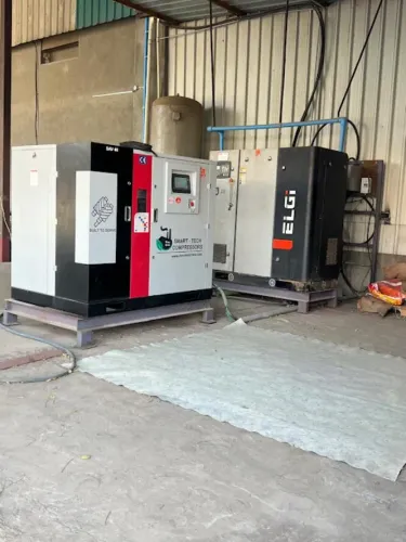
Use compressor sequencing when demand spans a wide range. A sequenced combination of a fixed-speed compressor and a VFD compressor can keep one machine near its efficient loading range, avoid conflicting pressure signals and reduce artificial cycling.
| Compressor type | Operating behaviour | Packaging-line fit |
|---|---|---|
| Rotary screw | Low pulsation, moderate discharge temperature, suited to continuous duty; wear rises with poor loading control | Continuous automated production |
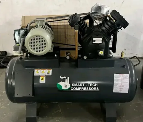
| Reciprocating | Higher pulsation and temperature, more valve and ring wear, suited to intermittent duty | Small or intermittent demand with suitable receiver capacity |
An air receiver tank buffers short blow-off or actuator spikes, reduces pressure fluctuation, limits rapid loading and unloading, and collects condensate. Size it from V = Q × t × p_atm ÷ (p_max − p_min), using free-air flow Q, peak duration t, allowable receiver pressure swing, and the minimum machine pressure p_min.
An oversized tank can prolong cycling; an undersized tank cannot control synchronized peaks.
Place a local receiver near an intermittent high-flow consumer when the compressor-room tank cannot stabilise its machine manifold.
How to keep pressure stable and turn a specification into a reliable installation
Pressure stability must be verified at the machine, not inferred from the receiver gauge. During compressed-air commissioning, run the filler, sealer, blow-off stations and actuators together, then measure pressure at the regulator and valve manifold. A high receiver pressure can hide transient losses through filters, hoses, couplings or restrictive valves.
1. Record pressure at each machine inlet during the highest-demand cycle. Compare the reading with the required bar(g), and note pressure sag, cycle timing and recovery time. Check that simultaneous demand, peak flow, receiver volume and documented leakage allowance support continuous operation.
2. Correct excessive consumption at the point of use. Replace open pipes or unrestricted fittings with engineered nozzles, air knives and flow restrictors, and size vacuum generators for the required transfer force. Raising plant pressure increases leakage and energy use without fixing poor device design.
3. Fit an automatic drain valve at each separator, receiver low point and filter. Route condensate to an approved collection or disposal arrangement. Inspect strainers, discharge lines and alarms, and define failure-open or failure-closed conditions: a failed-open timer drain wastes air, while a blocked drain can send liquid into the dryer, regulator and packaging equipment.
Zero-loss drains still need inspection and an alarm response.
4. Put these figures in the purchase specification: pressure, flow, dew point, complete ISO 8573-1 class, test location, peak demand, leakage allowance, receiver volume and maintenance access. Include packaging line maintenance tasks and intervals.
SMART - TECH COMPRESSORS can help match equipment, installation and servicing in Nagpur and Maharashtra, but select the system from measured line requirements and service capability, not a quoted horsepower figure.
Related products
 | Tank Mounted 10HP TANK MOUNTED MODEL FOR PACKAGING INDUSTRIES Tank mounted complete package rotary screw air compressor specially built for small industries with affordable prices and service. |
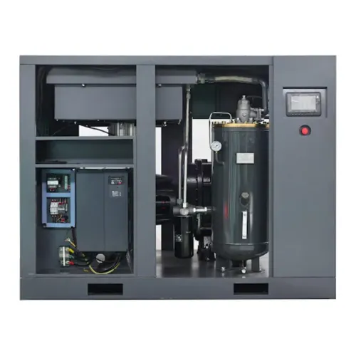
 | Rotary Screw Air Compressor Smart -Tech Compressors Upto 300 HP We brought Special customised machine for customers , very cost effective and breakdown free , long life with energy saving and low maintenance... |
Frequently asked questions
Where does compressed air work on a packaging line?
It powers filling and dosing valves, cylinders, clamps, grippers, capping, lidding, labelling and carton-forming equipment.
How should you size a compressor for packaging equipment?
Calculate the line’s required pressure and airflow, include peak simultaneous demand and pressure losses, then select capacity from those figures rather than horsepower.
What air quality does a packaging line require?
Choose filtration, drying and oil control according to product-contact risk, packaging requirements and pneumatic component limits; confirm the required ISO 8573-1 purity classes.
How do you keep packaging-line pressure stable?
Use a correctly sized receiver, compressor controls, dryer and distribution pipework, then verify pressure at the point of use during peak production.
Related products
 | Rotary Screw Air Compressor Smart -Tech Make 30 HP Fix Speed Compressor ₹310000 Smart -Tech compressors braught a customised machine for customers very good in Quality , low cost , energy saving , low maintenance cost , fast... |
 | Rotary Screw Air Compressor SMART -TECH MAKE 25 HP VFD COMPRESSOR ₹380000 Smart -Tech compressors braught a customised machine for customers very good in Quality , low cost , energy saving , low maintenance cost , fast... |
 | Rotary Screw Air Compressors braught a customised machine for customers very good in Quality , low cost , energy saving , low maintenance cost , fast service availability , and 5... View product → |
 | Rotary Screw Air Compressor 50HP SMART -TECH VFD COMPRESSOR PREMIUM MODEL PREMIUM RANGE ROTARY SCREW AIR COMPRESSOR 50HP VFD MODEL WITH VERY AFFORDABLE PRICE AND MORE WARRANTY THAN ANY BRAND |